SRW Design: Expert Level
Are you an architect, engineer, or contractor looking for more technical information as you design and install a segmented retaining wall (SRW)?
Guidance Manual
NCMA Guides
One of the best places to look for more information on SRW construction is the National Concrete Masonry Association (NCMA)
- Installation Guide
- Best Practices Guide (2016) Some parts of the Best Practices Guide have been pulled out and highlighted below to address common questions.
- NCMA SRW Design Manual (2009)
- Design Details (CAD files)
- Inspection Guide
Software Tools
Interested in designing an SRW, but don’t want to do the reading. There are several good software packages out there
Design Standards of SRW Block (ASTM C1372)
- Dimensional tolerances: ±1/8 in. (except for architectural finished surfaces)
- Minimum Compressive Strength = 3,000 psi
- Maximum Absorption = 15 – 18 pcf
Freeze-Thaw Resistance of SRW Block (ASTM C1262)
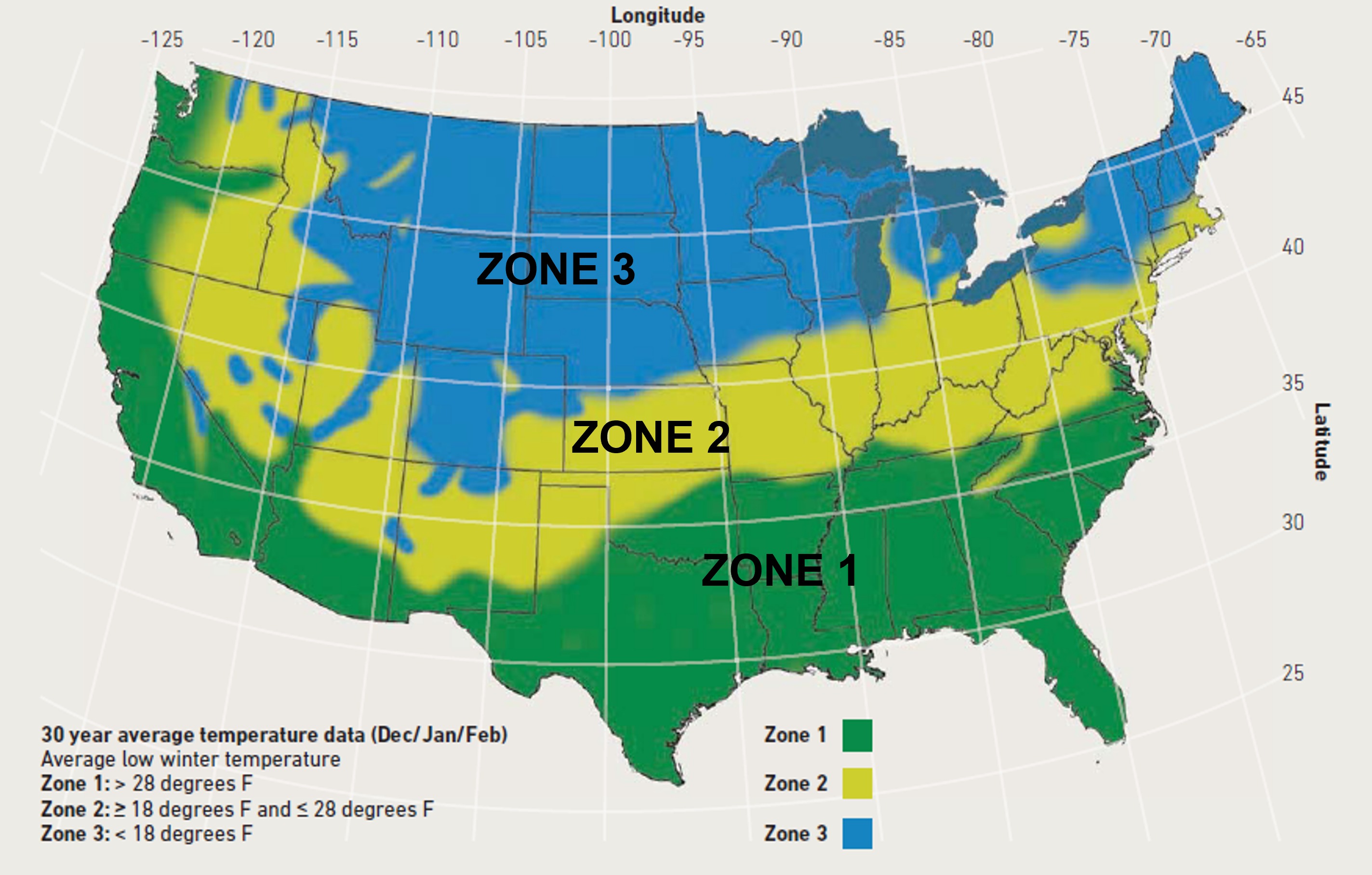
| Exposure Zone | SRW Properties | Freeze/Thaw Testing (C1262) |
| Zone 1 and Non-Roadway Applications | ASTM C1372 | None |
| Zone 2 –
no/negligible de-icing salt exposure1 |
ASTM C1372 | Proven field performance or test in water:
•≤1% wt. loss in 5 of 5 samples after 100 cycles; or •≤1.5% wt. loss in 4 of 5 samples after 150 cycles. |
| Zone 2 –
de-icing salt exposure |
ASTM C1372, plus
• Targeted compressive strength: 4000 psi • Targeted absorption: 7 pcf |
Test in 3% saline solution:
•≤1% wt. loss in 5 of 5 samples after 20 cycles; or •≤1.5% wt. loss in 4 of 5 samples after 30 cycles. |
Note: Only Zone 1 & 2 are shown because Ernest Maier does not service any regions that fall in Zone 3. Please see the Best Practices Guide for more information.
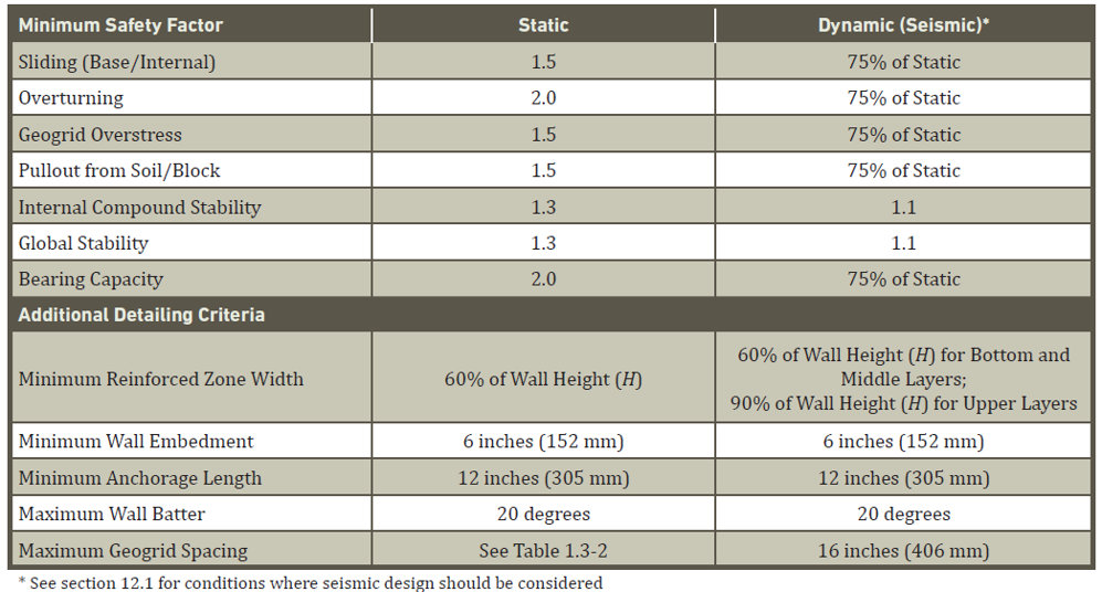
Minimum Design Standards
Appropriate design of an SRW should include a minimum safety factor. These are the minimum recommended safety factors.
Geosynthetic Reinforcement
Design Guidance
Use these design tables to understand how much reinforcement to place in your SRW
| Wall Height ft (m) | Reinforced Zone Material | Design and Layout Criteria | ||||
| Gradation | Plasticity | Reinf. Spacing, Max. | L/H, min. | Gravel Fill Thickness in. (mm) | ||
| H ≤10
(H ≤ 3) |
Recommended | See Table Below | Moderate | 24 in. | 0.6 | 24 in. (610 mm) from face
12 in. (305 mm) behind unit |
| Alternate | See Table Below
#200 waived |
Moderate | 16 in. | 0.7 | 30 in. (762 mm) from face
18 in. (457 mm) behind unit |
|
| 10 < H ≤ 20
(3 < H ≤ 6) |
Recommended | See Table Below | Low | 24 in. | 0.6 | Top 10 ft (3 m) same as
above, remainder 36 in. (914 mm) from the face, 24 in. (610) behind unit |
| H > 20
(H > 6) |
Recommended | See Table Below | Low | 24 in. | 0.6 | Top 10 ft (3 m) and lower 10
ft (3 m) to 20 ft (6 m) same as above, remainder 48 in. (1219 mm) from the face, 36 in. (914 mm) behind unit |
| Sieve Size | Percent Passing (Short/Medium Walls) | Percent Passing (Tall Walls) |
| 1 in. (25 mm) | 100 | 100 |
| No. 4 | 100 – 0 | 100 – 20 |
| No. 40 | 0 – 60 | 0 – 60 |
| No. 200 | 0-35 | 0-15 with PI<6 |
Material Choice
The proper use of geosynthetics, can compensate for many other imperfections, mistakes, or oversights in the design of an SRW. Be sure to select materials that provide the recommended material strength and are permeable to water.
An interesting application that showcases the power of geosynthetic reinforcement is: Geosynthetic Reinforced Soil- Integrated Bridge Systems (GRS-IBS). These are basically just SRW blocks with geotextiles every layer that are used for smaller bridges <140’ spans. These solutions are accepted by the FHWA and DOTs around the country.
Geosynthetic Reinforced Soil Integrated Bridge System
Drain Design
There are several drainage design options
- Blanket Drain- runs underneath the reinforced soil zone- used to address the presence of migratory subsurface water
- Toe Drain- located behind/below the SRW blocks- removes water from behind the blocks
- Heel Drain- located at the base of the interface of the reinforced and retained soil zones- drainage structure to further reinforce the
- Chimney Drain- located at the interface of the reinforced and retained soil zones- used to address high water tables or the presence of migratory subsurface water
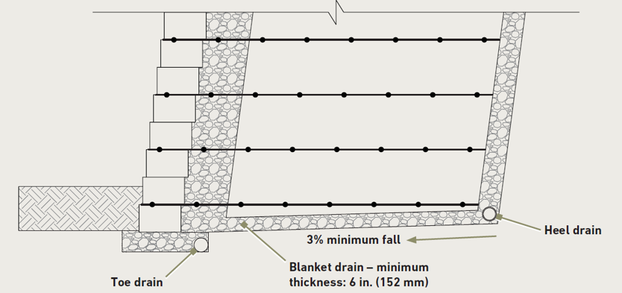
Toe and Heel Drain Detail

Chimney and Blanket Drain Details
Ernest Maier, Gomoljak Parker Block, and Skyline Brick have professional sales representatives who in many cases have served as contractors and installers ourselves. Feel free to reach out with your questions.

VP of Business DevelopmentAaron Fisher
Latest News
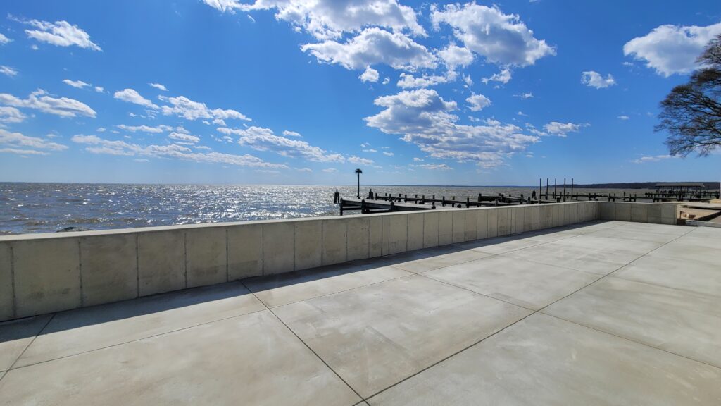
Building a Better Sea Wall
Waterfront property is the best: sea breezes, water access, and views. Unfortunately water and shoreline are always in a bit […]
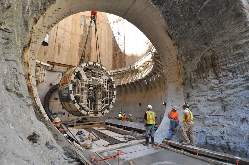
Stop Building Tunnels for Stormwater
Engineers love big projects. They are statements of competence, and also make big money. However, bigger isn’t always better and […]
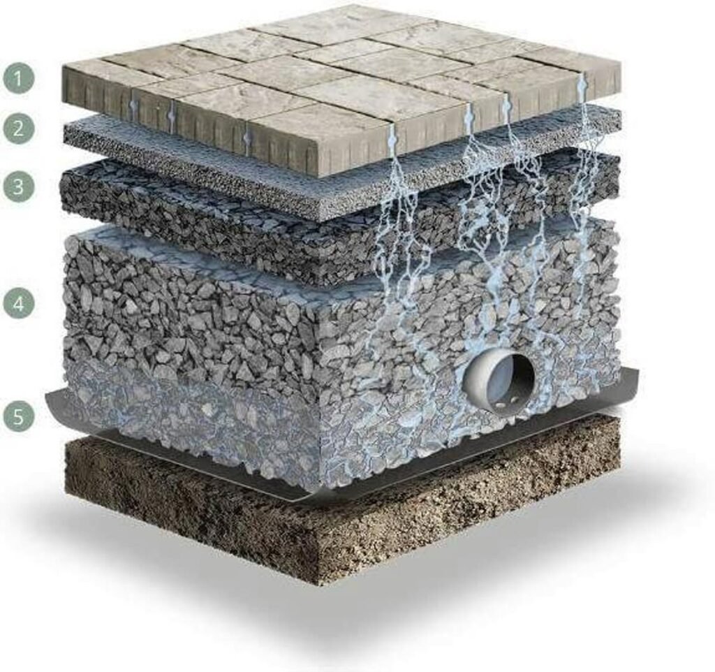
Understanding The Installation Costs Of Permeable Pavement
Permeable pavement has emerged as a leading solution in modern construction, known for its environmental benefits and ability to manage […]
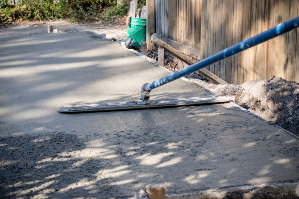
What Accessories Do You Need For Working With Concrete?
Working with concrete is an integral part of construction, whether it involves laying foundations, building structures, or creating pathways. The […]